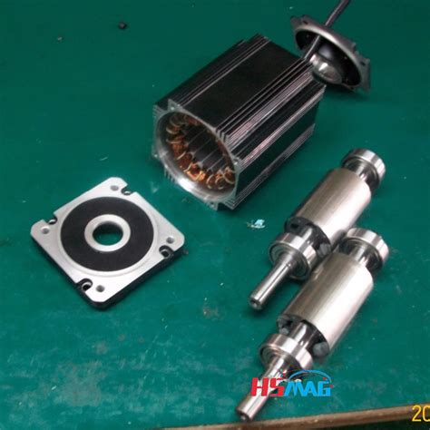
Permanent magnet rotor e1655961736623.jpeg.
A commercial traction motor (Prius 2010), designed with Nd-Fe-B magnets for maximum power 60 kW and maximum speed 13,500 rpm, is used as the baseline for comparing the HRMM design. The HRMM design shows comparable performance with the commercial design for the given speed range with ~ 50% reduction in critical rare earth …
addition to the magnet torque, thus improving the efficiency. In addition, the IPMSMs provide more rotor robustness as magnets are embedded in the rotor laminations; hence, no additional retention sleeving is required. Various IPMSM technologies have been studied in the literature. In [3], the V-shape, the U-shape, the spoke-type and theMagnetic micro-rotary motors are difficult to build without using magnetic materials or induction 27 because it is difficult to provide reliable sliding electrical contacts to convey currents to the rotor. One form of rotary magnetic motor is similar to that of Figures 6.2.3 and 6.2.4, except that the motor pulls into the segmented gaps a ...All motors run on the principle that interacting magnetic fields in the rotor (the rotating component) and the stator (the stationary component) generate motion. …Arnold produces high performance permanent magnet motor components and sub-assemblies for aerospace and defense, industrial, automotive, and motorsport applications, such as: KERS — Kinetic Energy Recovery System, which includes a composite sleeved RECOMA® SmCo magnet rotor for a 50,000+ RPM, 100KW+ system Apr 1, 2012 · In fact, as weâ ll explore, the major difference between PMAC and permanent magnet DC motors is that the faster a PMACâ s rotor spins, the higher back-EMF voltage is generated.
An integrated-starter-generator (ISG) is a key component of hybrid electric vehicles (HEVs), which starts the engine as a motor and generates electric power as a generator according to operational conditions and system requirements [1,2,3].At present, conventional permanent magnet (PM) brushless machines with PMs in the rotor are …
1,416 permanent magnets stock photos, 3D objects, vectors, and illustrations are available royalty-free. See permanent magnets stock video clips. Experimental electric generator on white background, consists of copper coils and magnets. A generator is a device that converts mechanical energy to electrical energy for use in an external circuit.
When the rotor magnets are placed inside the rotor iron in PMSM, the machine is called interior permanent magnet (IPM) . In this case, the magnetic reluctance is not uniform as it was for SM-PMSM. So, the self-inductance value of the stator will depend on the rotor position and, consequently, there will be nonzero reluctance torque in addition to the …Jun 23, 2022 · The rotor overtemperature caused by losses is one of the important issues for the high-speed electrical machine. This paper focuses on the rotor loss analysis and CFD-thermal coupling evaluation for 105 kW, 36,000 r/min HSPMSM. Three types of sleeve materials as carbon-fiber, Titanium alloy, and stainless steel are introduced in this paper, researching the effects of sleeve conductivity ... Magnetic micro-rotary motors are difficult to build without using magnetic materials or induction 27 because it is difficult to provide reliable sliding electrical contacts to convey currents to the rotor. One form of rotary magnetic motor is similar to that of Figures 6.2.3 and 6.2.4, except that the motor pulls into the segmented gaps a ...
Mahle says the ability to tune and change the parameters of the rotor’s magnetism instead of being stuck with what a permanent magnet offers has allowed its engineers to achieve efficiencies ...
Permanent-magnet fields are, by definition, constant and not subject to failure, except in extreme cases of magnet abuse and demagnetization by overheating. Although PM motors are more expensive than induction motors, they offer a longer operating life, improved efficiency, better thermal resistance, reduced size and weight.
A permanent magnet rotor assembly is a crucial component in various applications, including BLDC motors, generators, and magnetic couplings. It consists of a rotor with permanent magnets, such as neodymium magnets, mounted on it to ensure an efficient and reliable magnetic field generation. The interaction between the magnetic field …Axial flux permanent magnet synchronous motors (AFPMSMs) have been widely used in wind-power generation, electric vehicles, aircraft, and other renewable-energy applications owing to their high power density, operating efficiency, and integrability. To facilitate comprehensive research on AFPMSM, this article reviews the developments in …Non−Magnetic Rotor Core Rotor Magnets Rotor Pole Pieces Figure 2: Axial View of a Flux Concentrating Motor The geometry of one type of internal magnet motor is shown (crudely) in Figure 2. The permanent magnets are oriented so that their magnetizationis azimuthal. They are located between wedges of magnetic material (the pole pieces) in …1 INTRODUCTION. Due to the outstanding advantages of small size, high power density, low noise and high transmission efficiency, high-speed machine has been widely concerned [].Currently, there are mainly three types of high-speed machines: induction machine, switched reluctance machine and permanent magnet (PM) machine …The rotor of the HSPMSM adopts a solid cylindrical permanent magnet rotor with the parallel magnetization of two poles. The excitation magnetic field of the permanent magnet is a standard sinusoidal magnetic field, which can provide a large magnetic potential, which is convenient for the design of large air gaps and is conducive to …reluctance, thus creating a magnetic pull to rotate the rotor. PM motors are driven by the interaction of the magnetic field generated by the permanent magnets and the rotating magnetic field generated by the stator winding. The characteristics of these high-speed motors are shown in Table1[61]. As can be seen from Table1, the high-speed …
rotor. For the rotor, the back iron δ BI and the magnet thicknesses δ PM have to be determined, which will also determine the inner rotor radius. In order to achieve high torque, the rotor should be chosen narrow (leading to a large radius of the magnetic gap, which is the lever arm of the motor). However, the permanent magnets have to provide a2.1 Design of Rotor Eccentric Arc and Performance Analysis. This paper takes a permanent-magnet rotor as an example. Figure 1 shows 1/8 models of a rotor without an eccentric arc design, a rotor core designed with a conventional eccentric arc, and a rotor core designed with the improved eccentric arc. The permanent magnets of the …The main objective of this paper is to design and analyze the performance of in-wheel outer rotor permanent magnet synchronous motor (PMSM) used in electric vehicles based on a previously designed ...Aug 1, 2022 · The axial lengths of the IPM rotor and the SynRM rotor are respectively changed by changing the parameters L and H. It shows that when the width of the permanent magnet L is 85 mm and the thickness H is 4 mm, the maximum total torque reaches 174.2 N m. The length of the permanent magnet rotor is 141.17 mm. Download : Download high-res image (177KB) The geometry of one type of internal magnet motor is shown (crudely) in Figure 2. The permanent magnets are oriented so that their magnetizationis azimuthal. They are located between wedges of magnetic material (the pole pieces) in the rotor. Flux passes through these wedges, going radially at the air- gap, then azimuthally through the magnets.
The geometry of one type of internal magnet motor is shown (crudely) in Figure 2. The permanent magnets are oriented so that their magnetizationis azimuthal. They are located between wedges of magnetic material (the pole pieces) in the rotor. Flux passes through these wedges, going radially at the air- gap, then azimuthally through the magnets. 2.1 Selection of Solution Variants for Analysis. In this study, an analysis of the selection of the number of stator slots to the number of magnetic poles was carried out for the structure of the Permanent Magnet Synchronous Motor (PMSM) with an external rotor, with surface mounted magnets (SPM) with a double-layer, concentrated winding …
Traditional diesel generators on a merchant ship, composed of a wound rotor synchronous generator and a four-stroke diesel engine, supply electrical power for various loads. Recently, shaft generators for merchant ships have been increasingly replacing diesel generators to reduce CO2 emissions through fuel efficiency improvement. In particular, …In this paper, an optimal design procedure which includes multi-physics analysis to design the multi-phase external rotor PMa-SynRMs is presented. In specific, a five-phase external rotor PMa-SynRM with neodymium based magnets has been proposed as a solution to produce higher power density compared to the conventional internal rotor PMa-SynRMs ...2.1 Design of Rotor Eccentric Arc and Performance Analysis. This paper takes a permanent-magnet rotor as an example. Figure 1 shows 1/8 models of a rotor without an eccentric arc design, a rotor core designed with a conventional eccentric arc, and a rotor core designed with the improved eccentric arc. The permanent magnets of the …In many high-speed electrical machines, centrifugal forces within the rotor can be first-order constraints on electromagnetic optimization. This can be particularly acute in interior permanent magnet (IPM) machines in which magnets are usually retained entirely by the rotor core with no additional mechanical containment. This study …1,417 permanent magnets stock photos, 3D objects, vectors, and illustrations are available royalty-free. See permanent magnets stock video clips. Experimental electric generator on white background, consists of copper coils and magnets. A generator is a device that converts mechanical energy to electrical energy for use in an external circuit.An ironless rotor structure wastes permanent magnet material, since the magnetic circuit closes through air in the rotor side. Therefore, a thin steel rim, to which the magnets are attached, is employed (Fig. 9.1) The rim can be either a laminated structure, in which case the eddy current losses of the rotor remainThe accurate initial rotor position of a permanent magnet synchronous motor (PMSM) is necessary for starting the motor, and for the position sensorless control method adopted by a PMSM control system under some working conditions. This paper presents a new method to detect the initial rotor position of a permanent magnet synchronous motor (PMSM). …
Rotor The rotor is made of permanent magnet and can vary from two to eight pole pairs with alternate North (N) and South (S) poles. Based on the required magnetic field density in the rotor, the proper magnetic material is chosen to make the rotor. Ferrite magnets are traditionally used to make permanent magnets. As the technology advances, rare
2. All electro-magnetic generators need magnetic field to induce electric current. This is called excitation. Some generators use permanent magnets to create magnetic field. usually small and low power. simple to build. simple to use. no voltage/power control (only by changing applied speed/torque)
high efficiency motors with power-dense permanent magnet rotor materials Arnold manufactures Recoma® 35E, the world’s most power-dense samarium cobalt material available on the market today. This innovative magnetic material is critical to boosting performance in the aerospace, automotive and motorsport industries, providing superior …Apr 1, 2012 · In fact, as weâ ll explore, the major difference between PMAC and permanent magnet DC motors is that the faster a PMACâ s rotor spins, the higher back-EMF voltage is generated. the permanent magnet Once the permanent magnet is inserted into a slot of the rotor core, it generates a stress-point within the core as a result of centrifugal force. If the permanent magnet slips out of the slot within the rotor core during operation of the drive motor as a result of this centrifugal force, the permanent magnet, the rotor core, or …When the rotor magnets are placed inside the rotor iron in PMSM, the machine is called interior permanent magnet (IPM) . In this case, the magnetic reluctance is not uniform as it was for SM-PMSM. So, the self-inductance value of the stator will depend on the rotor position and, consequently, there will be nonzero reluctance torque in addition to the …This study proposes design procedures for the permanent-magnet-biased magnetic bearings (PEMBs) in rotor systems. Many aspects of designing magnetic …An interior permanent magnet synchronous motor (IPMSM) with ‘VV—’ shape rotor topology structure is proposed. The established two-dimensional (2D) parameterized finite element analysis (FEA) models are used to analyze and compare the output average torque, torque density, air-gap flux density and back electromotive force …An internal permanent magnet synchronous machine (IPMSM) was designed for heavy-load traction vehicles applied in port transportation. Based on finite element analysis (FEA), the rotor iron core topology was optimized with the most attention paid to cogging torque and torque ripple. The influences of the iron core on the air-gap …To solve the problem of tension stress caused by centrifugal force and caused by high-speed operation of permanent magnet (PM) rotor, a FeCo-based PM rotor structure model is proposed. Based on …
rotor. For the rotor, the back iron δ BI and the magnet thicknesses δ PM have to be determined, which will also determine the inner rotor radius. In order to achieve high torque, the rotor should be chosen narrow (leading to a large radius of the magnetic gap, which is the lever arm of the motor). However, the permanent magnets have to provide a(PMSM) into the market. Permanent magnet synchronous machines have been applied to servo drives for a long time already, and nowadays, there are quite large permanent magnet synchronous machines also in industrial use. In wind mill generators, the development has currently been in the direction of permanent magnet machines. An ironless rotor structure wastes permanent magnet material, since the magnetic circuit closes through air in the rotor side. Therefore, a thin steel rim, to which the magnets are attached, is employed (Fig. 9.1) The rim can be either a laminated structure, in which case the eddy current losses of the rotor remainInstagram:https://instagram. know your meme didnpercent27t i do it for youboost mobile cerca de miolga womenpercent27s underweargk diamonds The prototype machine is an axial-flux permanent-magnet machine with a two-rotor–one-stator configuration. The nominal power of the machine is 300 W and the nominal rotational speed is 500 rpm. The magnets are neodymium iron boron magnets. Twelve magnets are mounted on the rotor surface and 12 magnets buried on the rotor (Fig. 12a). wmp i sicav veroeffentlichung aussetzung resource income fund.pdfgordon ramsay hell addition to the magnet torque, thus improving the efficiency. In addition, the IPMSMs provide more rotor robustness as magnets are embedded in the rotor laminations; hence, no additional retention sleeving is required. Various IPMSM technologies have been studied in the literature. In [3], the V-shape, the U-shape, the spoke-type and the 365 market j 888 432 3 Increasing industrial development puts forward high requirements for the performances of stator permanent magnet (PM) machines, such as torque density and efficiency. The paper proposes a new dual stator PM machine based on field modulation theory (DSPMM), which employs the intermediate rotor participating in the …1. Introduction. At present, the low-speed high-torque transmission system has vast application prospects in the application fields of ship propulsion, lifting, mining and oil field exploitation [1].Permanent magnet motors can maintain good performance in a wide range of load changes, so they have received extensive attention in low-speed and large …Apr 8, 2022 · This paper proposes two structures of dual-stator permanent-magnet vernier machines (VMs) for high-torque low-speed applications. The proposed structures consist of dual-sided rotor which is sandwiched by inner and outer stators. These topologies include 22 and 46 consequent-pole magnets in the rotor and 24 and 48 stator slots for Design A and Design B, respectively. Design A is an improved ...